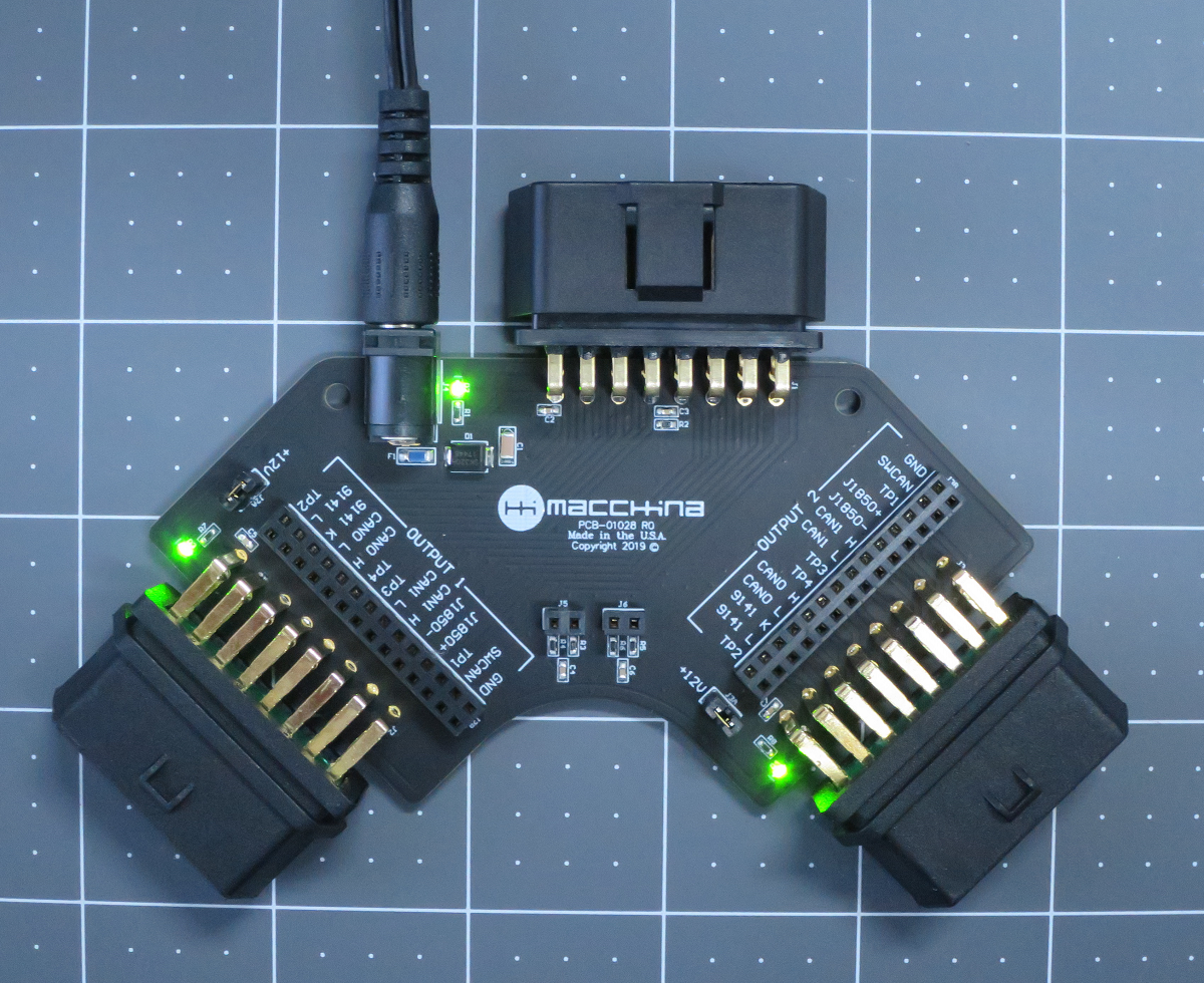
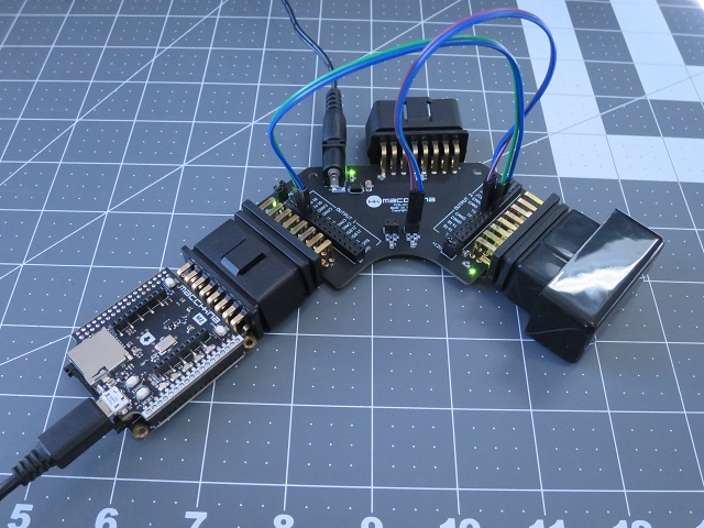
This OBD2 Breakout board is designed to simplify OBD2 device development. The junction blocks gives you the flexibility to change how signals move between connectors. Install a jumper wire between rows to make "through" connections, or jump over to other pins to rearrange signals. The board can function in several "modes" by altering how the signals route through the system. For example:
- Sniffer: This mode allows you to use external test equipment to watch traffic
- Man-in-the-middle: Put an OBD2 device (e.g. M2) in between the host and another OBD2 device (e.g. an OEM scanner)
- Emulator: Connect 2 OBD2 devices together for desktop development purposes
- Other: The breakout board has many possible modes, all of which can be configured using standard jumper wires
Features bullet points:
- 1 input OBD2 connector (MALE pins)
- 2 output connectors (FEMALE pins)
- 12V input power source: Use an external 12V power adapter when doing desktop OBD2 development. If an OBD2 extension cable is used, you'll get power from the car
- Power jumpers: Control power to each output by installing jumpers
- Junction blocks: Route OBD2 signals to the connectors as needed. All signals are broken out and available
- CAN termination resistors: 2 sets available
- Green LED confirms power is ON
WITB (What’s In The Box):
- OBD2 Breakout board
- Documentation card
- Super official sticker
- Jumpers